LUT
LUT : creation, interpolation, converion
WonderLookPro create set of LUTs based on the various settings regarding color reproduction, if devices are connected, send Luts to them in no wait to reflect the result of user interface control. WonderLookPro's design make users don't need to know about what is LUT in this context.
But, in some cases, like using different type of LUTBOXes, exporting LUTs in file form to use on other third party software, it may be better to know about technical aspects of LUTs, because un-proper creation or use of LUTs might bring unexpected result. You can refer to here about general LUT technology topics so here I will explain about how WonderLookPro manage LUTs.
For almost all users, LUT is to exchange color transform information between applications or devices, so it is kind of a blackbox for you making the system or software take care about it. We, makers, are trying to implement LUT related functions with our best to fulfil users high expectation, which means, the LUT related funcitons should be highly compatible and high enough quality. WonderLookPro generates LUTs when necessary with good enough quolity, interpolate LUTs with high accuracy algorithm, converts input/output color space of LUTs if necessary.
Creation of LUTs
We've already explained about WonderLookPro achieved various transforms based on ACES architecture. Suppose we are going to make following transform.

We can write down to more detailed diagram as below.
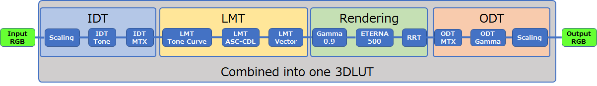
In this regard, there 12 steps calculations, in detail more and more calculations will be made to achieve this entire transform. WonderLookPro makes LUTs, all of the transforms are conbined into one set of LUTs. If user changes one ASC-CDL parameter by user interface, all of the calculation process will be made from scratch to create new LUTs.
Once we've got made LUTs, we can get the results of the transform by simple method like this.
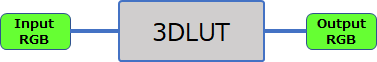
Just apply the LUT to input RGB to get output RGB. The box means LUT interporation to create output RGB from input RGB. In WonderLookPro, LUT interpolate calculation is used to convert image or picked pixel numbers, to send LUTs with no delay to LUTBOXes if connected, to create LUT files when exporting.
To make good quality of LUTs, we have to improve the quality about every steps of calculations. Even a small amount of errors could bring huge error becase we are cascading 12 or more steps of calculations. WonderLookPro is using double size floating point numbers to make accurate calculations, and is using mathematical equations if possible instead of LUTs to avoid interpolation errors, to improve the quality of LUTs as much as possible.
Interpolation of LUTs
We often use this expression "apply LUT to the image". In the strictly correct expression, it is, to apply LUT interpolate calculation to the input image to get new processed image. The process of LUT interporate calculation is applying following procedure to all of the pixels of the image.
1. Extract one pixel RGB information
2. Calculate LUT interpolation of input RGB value to create new RGB value
3. Replace the new RGB value to the place where input RGB extracted
The interpolation calculation always has error. To increase the grid count of the LUT, which means to use larger size of LUT, reduces error. But the system resource is limited and there would be limit of the grid size, and it may take longer time to create the LUTs than requred performance. One more items to affect the amount of error is the algorithm of the interpolation. Based on our explanation, in most cases, the triangular interporation brings better reuslt than popular cubic interpolation. Off course IS-mini and IS-miniX is using triangular interpolation, and WonderLook is using it to create and convert LUTs. We are showing more detailed explanation and experiment about the algorithm of interpolation here.
Utilization of existing LUTs : Conversion of input / output color space
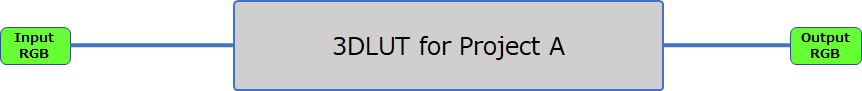
Once LUT is created, you can not deconstruct the 12 steps of transforms in the above example again. You have to use the LUT as it is.
But WonderLookPro provides the means to replace the input and / or color space of the existing LUT. We will show the example how it works.
Suppose you've created the LUT form the following transforms.
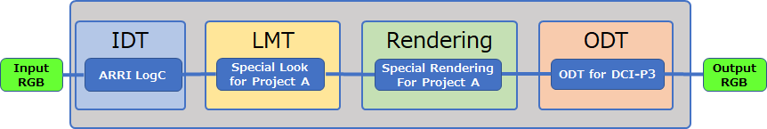

This LUT is supposed to input ARRI LogC signal, supposed to output DCI-P3 projector, so you can not use the LUT to other cameras or other monitors. Even if you used it for other ones, you can not get the proper result.
But WonderLookPro can do following transform.
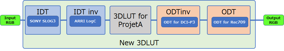
As the pre transform of the main LUT, it is inserted SONY SLOG3 transform and ARRI LogC's inverse transform. As a result, whole process will act as it is the LUT made for SONY SLOG3 input. As the post transform of the main LUT, it is inserted inverse transform of DCI-P3 and forward transform of Rec709. As a result, whole process will act as it is the LUT targeting for Rec709 instead of DCI-P3.
Creating new LUT by this mehod makes us to use it for SONY SLOG3/Rec709 project. Off couse, there is interpolation error or gamut size difference so we can never get exactly the same result, but we will be able to get goo enough result which is very close with the previous project, ARRI LogC/DCI-P3.
LUT evaluation / confirmation
3DLUT consists from the array of numbers, and you can not tell what kind of transform just by looking at the numbers. WonderLookPro is using system tone curve graph to visualize the transform of the LUT to confirm the property of the transform.
Here is the system tone graph of the LUT which converts Rec709/2.4 to Rec2020 to PQ.
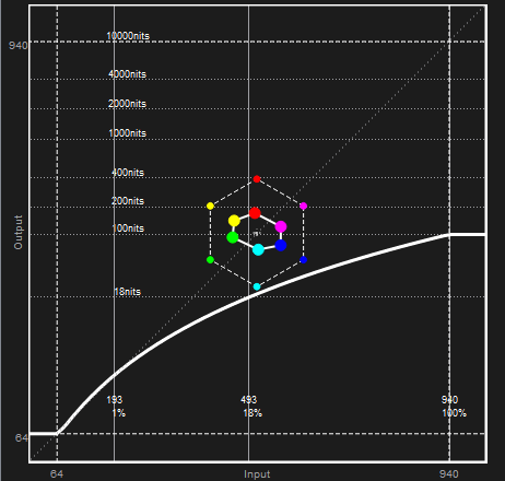
Horizontal axies is input, Rec709/2.4, vertical axis is output, Rec2020/PQ. Both input/output is defined in legal range, whihc is from 64 to 940 in 10bit scale. There is "100% " notation at 940 in the horizontal axis, and it matches the maximum value of Rec709/2.4 definition. On the other hand, the maximum brightness on the vertical axis shows 10,000nits at 940, and it matches maximum brightness of PQ definition. The maximum vertical value of the curve is around the middle of the vertical axis, which os just 100nits. It means Rec709/2.4 100nits input was transformed to Rec2020/PQ's 100nits. We could confirmed the LUT was created as expected so far.
The hexagon on the middle is showing the change of colors for representive 6 colors in hure/ saturation vector axis. The center is achromatic, outer side is more saturated. (It means not real saturation, but relative saturation level in its color space) The regular hexagon with dotted lines shows the position of the input 6 colors. The transformed hexagon with solid line and with larger circle on the corner is the LUT processed position of the colors. We can read form the diagram that the relative saturation of these colors decreason by the transform. The gamut of Rec2020/PQ is larger than Rec709/2.4, so if you pick the correnponding number of the same absolute color from both space, the color difference of Rec2020/PQ, which relates to relative saturation is smaller than Rec709/2.4. That is, the relative saturation looks decreased. It is the right direction of this transform, so we could confirm that the LUT was propery created.
Thus, sytem tone curve graph is very useful to evaluate the created LUT. We strongly recommend WonderLookPro users to master how to read this graph and use it for the confirmation of the settings.