
Hi, everybody. I am Onishi of TVLogic.
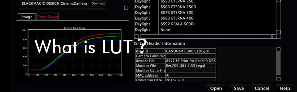
When we change the color of an image, we usually call it "generating a LUT".
We usually use this term, so we know the meaning of what occurred on-set, but most people don't actually know the meaning of the word "LUT."
On this page, I would like to further explain some information related to LUTs.
I hope this page removes any vagueness you may have on LUTs.

- Lesson 1: Basics about LUT.
- Lesson 2: What is 3D LUT?
- Lesson 3: Necessity for interpolation and accuracy of LUT.
- Lesson 4: Relationship between arithmetic equation and LUT.
- Lesson 5: What is the role of LUT on color conversion on the image.
- Lesson 6: How can we apply LUT in realistically?
※The contents of the lesson are subject to change.

Lesson 3: Necessity for interpolation and accuracy of LUT.
It has been a long while since the last update. This time, I will explain meaning and effect of the grid number of Look up tables and show the result of the experiment regarding the grid number of LUTs.
Let's try to make 3DLUT in 8bit color space. 8bit color space color is represented by 256 kind of integer from 0 to 255.
The number of all of the colors in this spaces is 256 x 256 x 256 = 16,777,216, 16 million, it means this number of table items are required to define the transformation.
Here is the example of the table.
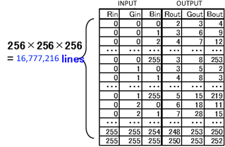
figure 1
If the output color space is 8bit as well, the size of the table is 16,777,216 * 3 = about 50MB. It is not so small but not too big to use in the system.
Then, what about the 10bit color space which is the most popular in motion picture images.
10bit color space consists from 0 to 1023, so the items required for the table is 1024 x 1024 x 1024 = 1,073,741,824 (about 1 billion).
If the output color space is 10bit as well, the size of the table is 1,073,741,824 * 4 = 4GB, quit a big size.
It is virtually impossible to implement into the image processing system to be used for real time, create instantly or switch multiple table instantly.
How about floating point color space? It is impossible to prepare the table which covers all of the input values.
Then we will use "interpolation" to cover all of the input values.
This method is not to prepare all of the combination in the input color space,
but to prepare discrete number of items of the table as grids and to interpolate to get estimated output value for outside of the grid input colors.
For example, the following table consists from discrete number of the input which increase 20 one by one.
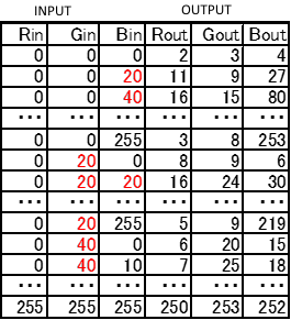
figure 2
The output of the input (0, 0, 30) which is between the grid,
can be calculated by the average of the output value of the input (0, 0, 20) and (0, 0, 40) which outputs are (11, 9, 27) and (16, 15, 80).
This method enables to represent the transform which was needed to be defined by the huge table, by the quite a small table.
But this "interpolation" method creates errors, not to be assured to get accurate values.
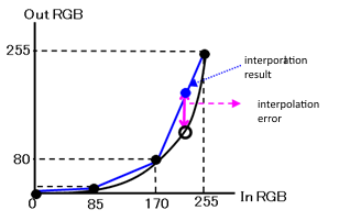
figure 3
Here is the example by using simple 1DLUT interpolation.
This is the example of 8bit color space 1DLUT represented by the 4 grids.
Black curve is the correct transform and the table consists from four black circle points.
The interpolated value of the input value 200 is about 180 which is shown in blue circle,
which has a big error compared to the correct value shown in white circle.
Increasing the number of the grid decrease the error of the interpolation.
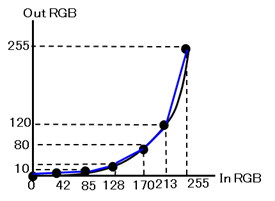
figure 4
This example is the result of 7 grids for the same transform.Compared to the figure3, the difference between black curve and blue lines are very small.
It means the error of the interpolation is decreased.
On the other hand, the error of the interpolation varies by the characteristic of the transform.
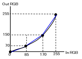
figure 5
This example uses 4 grids which is the same number with figure3,
As shown above, the interpolation has errors but the size of the errors varies by the conditions.
For 3DLUTs, we usually uses 17 grids, 33 grids, or 65 grids for the number of the grids.
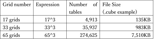
It is obvious that the bigger the number of the grids the smaller the interpolation error, it means higher preciseness. Instead of this merit, file size and the memory size is bigger so it will take time to handle the data, or it requires higher specification system, which are the deficit of using bigger number of grids. In usual cases, 33 girds are most popular, and 65 grids would be used for the if the system available, to achieve better quality.
Then let's take a look at the result when we use different grids number 3DLUT.
We used the conversion of HDR/SDR from Rec2020/ST-2084 to Rec709/2.4.
The data for the input was chosen for cyan gradation after evaluation of many type of gradations.
Image1 is the input image,and figure6 is the figure of the R channel.
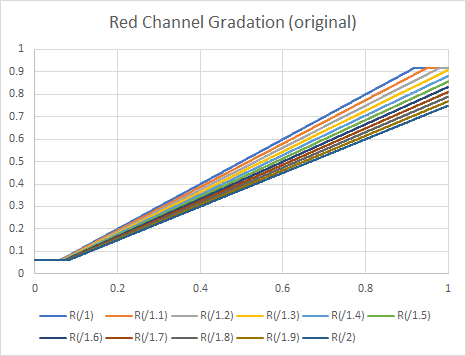
figure 6

Image2 and figure7 are the correct results calculated by the numerical transform .
The correct result by the numerical.
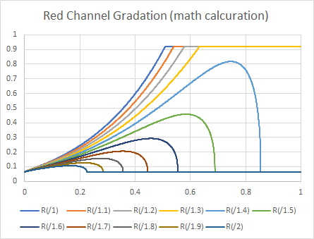
figure 7

It has very strong non-linearity, so it seems very difficult to represent the transform by 3DLUT.
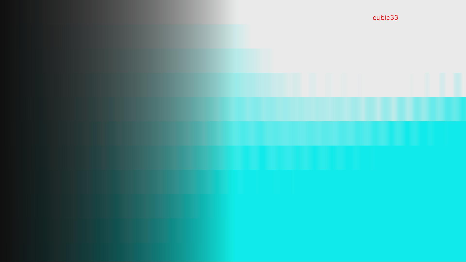
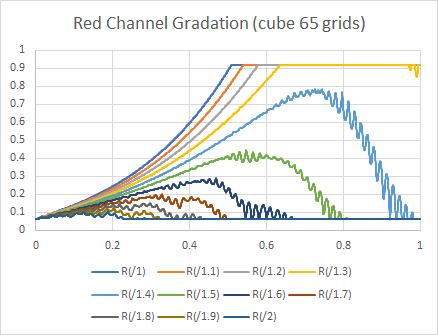
Here is the results of cubic interpolation which is the most popular interpolation method.
17 grids
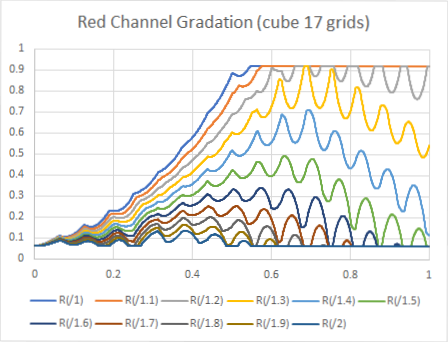
figure 8

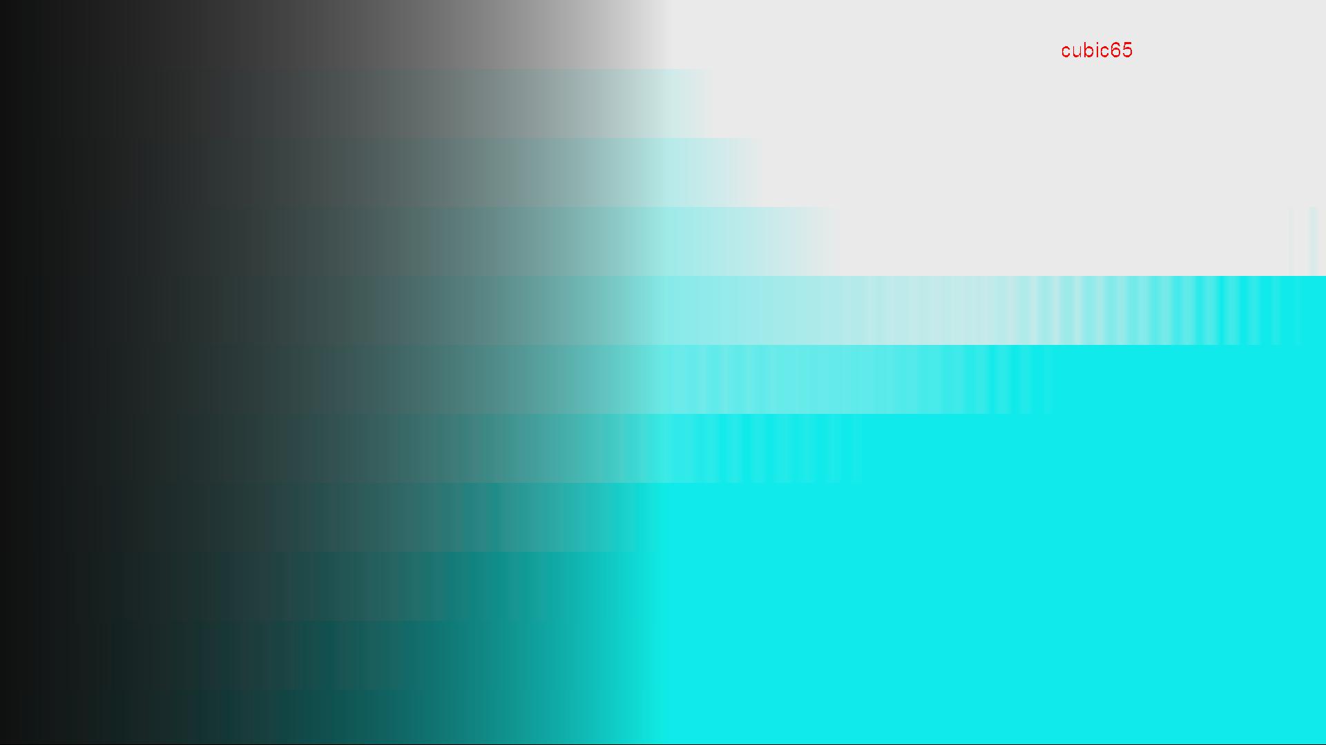
129 grids
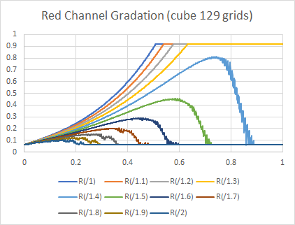
figure 11
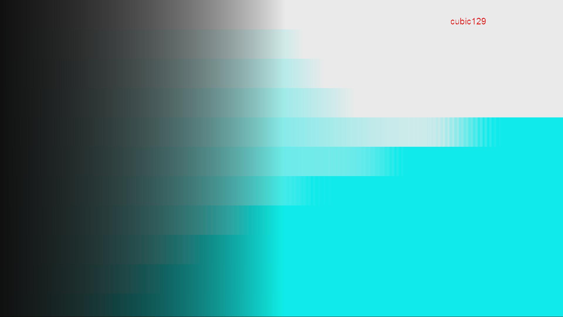
For 17 grids result, we can see quit a big range of banding and we can observe on the image too.
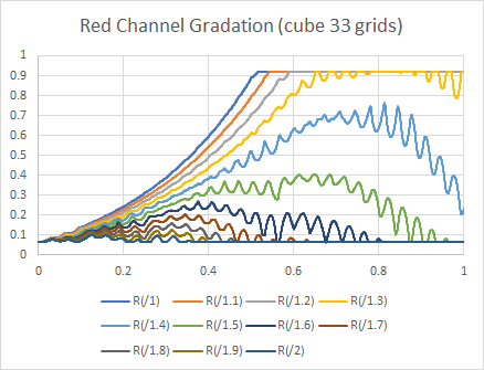
If we increased the grid number, the range of the banding decrease and the frequency of the oscillation also decrease
but it did not disappear even at the highest grid number, 129 result.
This figure shows the comparison between the math calculated result and various grid number results.
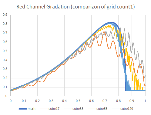
figure 12
Small number of grids shows not only banding problem but also shows big error compared to math calculation result.
Increasing the number of the grids improve both quality and banding, but even 129 grids results remains the error and banding.
These banding and errors depend on the algorithm of the interpolation.
The interpolation used on the experiments so far was cubic interpolation.
IS-mini is using triangular interpolation, which creates less banding and less error than cubic interpolation,
to achieve good enough quality by using 26 grids, a little bit smaller number for the grids for typical 3DLUT.
Figure13 and image7 show the results of the processing of IS-mini.
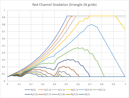
figure 13

Here is the comparison of the result of triangular interpolation of IS-mini with various grids of cubic interpolations.
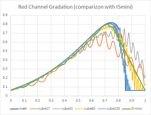
figure 14
IS-mini's interpolation quality is almost equivalent with 65 grid of cubic interpolation, and IS-mini's banding is the least in any other number of grids result.
The results of this experiment is under HDR to SDR conversion, using cyan gradation for the input.
It is very limited comparison but the result matches with any other evaluation result.
By summarizing so far,
1. 3DLUT grid number '33' popular is populate but we should use 65 grids if possible.
2. Triangular interpolation is better quality, which means less banding, less errors which is equivalent to the double size grids for cubic interpolation.
See you next time!